

Tuesday, August 25, 2009


Civil and environmental engineers are concerned with some of the most pressing problems of our world, including public infrastructure renewal, access to clean drinking water, environmental remediation and sustainable solutions to energy needs.
The CEE undergraduate program prepares students to face these tremendous challenges by providing a sound education in math, physics, and science and engineering fundamentals, all while emphasizing hands-on design projects and case studies that supply context and motivation. Students are taught how to combine theory, measurement and modeling to develop a good understanding of the problems at hand and point the way to desirable solutions.
The three CEE undergraduate degrees - civil engineering (1C) environmental engineering science (1E) and civil and environmental engineering degree (1A) - share a common core, usually taken in the sophomore year, that includes subjects in ecology, mechanics, mathematics and engineering design. In the junior and senior years, students build on the core by taking more specialized subjects in their chosen degree tracks.
The CEE engineering design lab sequence introduces sophomores to design and fabrication in a supportive team-oriented environment. The Classes of 2009 and 2010 designed and built energy-harvesting machines, for instance, a bicycle that harvests and stores the energy generated by the cyclist and a turbine that collects wind energy. Students in the senior engineering design class also design and build projects, including full-scale portable footbridges that can support a ton of concrete blocks.
Our departmental unit requirements are among the lowest in the School of Engineering, providing flexibility for students who wish to have a minor as well as a major, study abroad and pursue interests outside engineering.
Schematic Symbol Reference
This is an offline version of the . It contains all the same info, but is a standalone program that requires no Internet connection to run. This will run under Windows 95, Windows 98 and NT4 Server and Workstation.
If you have the filesMSVBVM50.DLL and MSVBVM60.DLL in your windows\sytem directory, then you can download the (917K). Otherwise, you will need to
If you have built any of the interfaces on my circuits page and now want to know how to actually make use of them, this page is for you. This is a simple introduction to programming the parallel port in QBasic, QuickBasic or similar language. Note that most of the concepts in this page can also be applied to GWBASIC. If you are interested in using Visual Basic to control the port, see Programming The Parallel Port In Visual Basic. What this document will not do is give you lots of details on using bi-directional ports, DMA and other advanced topics. This document assumes that you are familiar with the basic functions of BASIC itself.
The parallel port is made up of three different sections. These are the data lines, control lines and status lines. There are 8 data lines, and they are the primary means of getting information out of the port. In simple projects, you will be concentrating mostly on the data lines. The control lines are another 4 outputs. They are meant to provide control signals to the printer (such as form feed or initialize). The status lines are a standard parallel port's only inputs. There are 5 of them. They were meant to allow the printer to communicate things such as error, paper out and busy to the PC.
Each section is accessed by it's own address and will act independently from the rest. This is almost as if they were different ports. The addresses are as follows:
| Data Lines | ||
| Control Lines | ||
| Status Lines |
You need to know the address of the port you want to use. You will also need two other things; the command to access the port and the number you want to set it to. The command will be explained in a little while. The ports work with numbers. These can be expressed in hex, binary or decimal, but for this document all values will be expressed in decimal. It's just easier that way. Anyway, you operate the port by sending it a number that represents the binary pattern of the physical outputs on the port. For example, to set the 8 data lines to 11111111, you would send 255. To set them to 00000000 you would send 0. Note that these are all 8 bit binary numbers, and the port is also 8 outputs. Coincidence? I think not.
Now that we know how to tell the port what bit patterns we want, we have to actually apply that to the BASIC language. BASIC uses two commands to talk to the computer's ports. These are OUT and INP. OUT is a statement and is used like the following:
OUT [port],[number] We will get to INP later. As you can see, the two parameters required are the port address and the value we want to set it to. The address can be decimal or hex, as can the value. Because there are only 8 data lines, we can only send a maximum of 255 to the port (255 is decimal for binary 11111111). The examples below illustrate sending a few different bit patterns to the data lines.
'set port to 00000000
OUT 888, 0
'set port to 10000000
OUT 888, 1
'set port to 01000000
OUT 888, 2
'set port to 00100000
OUT 888, 4
'set port to 00010000
OUT 888, 8
Of course, you can also turn on more than one bit:
'set port to 10110000
OUT 888, 11
Note that when you send a bit pattern to the port everything that was there previously is cleared. This is a convenience and also a annoyance. For example, what if we want bit 2 to always stay at 1, but want to turn bit 5 on and off in sequence? Every time we set bit 5, bit 2 is turned off, and vice versa. We will discuss how to get around this when we get to the INP function.
The control lines are just as easy to control, but there are a few differences. First, the address of the port is 890. Second is that there are only 4 outputs, so the highest decimal representation of the binary bit pattern you will be using is 15 (binary 1111).
Outputting information is easy, and inputting is just as easy. If you actually want to get information into the computer, you will be using the 5 status lines. Reading the bit pattern of a port is done using the INP function. This function is used in the following way:
[variable]=INP([port]) So if we wanted to get the current status of the status lines (port 889) we would use:
PortNum%=INP(889) PortNum% would then contain the decimal representation of the binary bit pattern present at the 5 status lines. If you try this and get 31 (11111) with nothing connected to the port don't be surprised. When there is nothing connected to the input of a TTL logic chip, a high input is usually assumed.
Not only can you perform inputs on ports actually designed for inputting, but you can also use INP to read the status of an output port. For example:
PortNum%=INP(888) The above would set PortNum% to the current value of the data lines (port 888). We can prove this by doing the following:
OUT 888, 56
PortNum%=INP(888)
PRINT PortNum%
If all is well, the number 56 will appear on the screen.
Now that we know the INP function we can use it to solve the problem of keeping the state of one bit while changing the state of another. For that we will define a subroutine that uses both functions:
SUB OutPort(PortAddress%, OutNum%)
PortState% = INP(PortAddress%)
PortNum% = PortState% + OutNum%
OUT PortAddress%, PortNum%
The sub does all it's normal stuff, but also sets the port to 0 if a 0 was passed to it. This is a very easy to clear up a port if you create strange bit patterns by trying to turn a bit on twice. You may want to keep track of the state you expect the port to be and compare it to the actual state by using the INP function. If the two do not match, clear the port and reset all the the bits using your other variable.
Now that we know a few useful functions with respect to output, we should look at a very useful input function. When using the port in software, you will very likely need to know the status of a single bit at one time or another. There are various ways of doing this, but I find the function below to be the most useful:
FUNCTION BitStatus(PortAddress%, BitYouWant%) AS INTEGER
IF PortAddress% = 888 THEN
NumOfBits% = 8
ELSE IF PortAddress% = 889 THEN
NumOfBits% = 5
ELSE
NumOfBits% = 4
REDIM PortBits(NumOfBits%) AS INTEGER
PortNum% = INP(PortAddress%)
FOR i = 1 To NumOfBits%
PortBits%(i) = PortNum% MOD 2
PortNum% = FIX(PortNum% / 2)
NEXT I
BitStatus% = PortBits%(BitYouWant%)
The function first decides how many bits it has to work with by looking at the address of the port. Note that in all other examples it was really irrelevant if you used decimal or HEX addresses. In this function you will need to change the numbers if you work in HEX. Now, back to how the function functions (he he he). After deciding how many bits there are in the port, it makes an array of the same number of elements. It then goes through a loop, performing integer division on the number returned from the port. It performs one division for each bit in the port. This is probably the easiest way to convert to binary, as BASIC has no built in decimal to binary function. Again, if you work in HEX you will have to adjust the function here. The function then assigns itself the value of the array element you specify with the BitYouWant% variable.
For example, to read bit 5 of port 888, you would use:
Bit5Variable% = BitStatus%(888, 5) Well, that's it. The above is not limited to the parallel port. You can use it with any sort of interface that uses a standard I/O port. Of course, this code would not be ideal in controlling the serial port, as a lot of low level coding would be necessary.
Electronics is unfortunately related to lots of math. Included here are several electronics calculators to help take the load off your brain. Just plug in your numbers, hit "Calculate" and the page does the rest. Note that I am by no means a math whiz, and therefore have included only the most basic formulas. If you have a formula that you believe is important, then just and I will add it to this page. If for some reason you get an answer that is "NaN", "Infinity", or other such message it means that the script cannont handle the numbers you put it.
Resistors
Calculates up to four resistors in series. All values in Ohms.
| | R2:
| R3:
| R4:
|
| Calculated Rt:
|
| ||
Calculates up to two resistors in parallel. All values in Ohms.
| R1:
| R2:
| |
| Calculated Rt:
| ||
Calculates up to three resistors in parallel. All values in Ohms.
| | R2:
| R3:
| |
| Calculated Rt:
|
| ||
Parallel Capacitors (C1+C2=Ct):
Calculates up to four capacitors in parallel. All values in uF.
| | C2:
| C3:
| C4:
|
| Calculated Ct:
|
| ||
Calculates two series capacitors. All values in uF.
| C1:
| C2:
| |
| Calculated Ct:
| ||
Calculates up to three capacitors in series. All values in uF.
| | C2:
| C3:
| |
| Calculated Ct:
|
| ||
Calculates a voltage (V) from a current(I) and a resistance(R). Resistance is in Ohms. Current is in Amps. Voltage is in Volts.
| | R:
| |
| Calculated V:
|
| |
Calculates a current(I) from a voltage(V) and a resistance(R). Resistance is in Ohms. Current is in Amps. Voltage is in Volts.
| | R:
| |
| Calculated I:
|
| |
Calculates a resistance(R) from a voltage(V) and a current(I). Resistance is in Ohms. Current is in Amps. Voltage is in Volts.
| | I:
| |
| Calculated R:
|
| |
Calculates a power(W) from a voltage(V) and a current(I). Power is in Watts. Current is in Amps. Voltage is in Volts.
| | I:
| |
| Calculated P:
|
| |
LED Series Resistor Value ( R=(VSupply-VLED)/LEDCurrent) ):
Calculates the correct value for the dropping resistor(R) used in series with an LED. VSupply is the supply voltage in volts. VLED is the LEDs operating voltage in volts. LEDCurrent is the current required by the LED in Amps.| LED Voltage:
| LED Current:
| ||
| Calculated R: Ohms |
| ||
Plan your project out on paper, noting down all parts required, where those parts may be obtained and if possible the price of each part. Be sure that you can get all the parts necessary before starting the project. It is very annoying when you spend $30 on parts only to find that you can't get a specific IC. If none are present, write down the steps to take when assembling the project. Look over the steps three times to make sure you are working in a logical order. Remember that smaller parts are to be soldered/bolted/etc. before larger parts, unless there is an obvious reason to follow a different order. Flow charts can also help.
Gather and organize all materials before you start placing and soldering parts. This way, you know exactly what you have and where it is before you have to keep track of a hot soldering iron.
Soldering on resistors, diodes, jumper wires and other such parts will make it much easier to put the thing together than soldering large capacitors, transistors and ICs on first will.
After soldering each component, make double sure that it is the right component in the right place. Also check for cold solder joints. 90% of all circuit failures are due to incorrect component placement or poor solder joints.
It is a good idea to test circuits on a solderless breadboard or other prototyping equipment before assembling a "good" version. Errors do creep up in magazines or on Web sites, so an easily changeable test version of the circuit is great in case you need to work out the bugs. When assembling circuits from magazines, wait a month or two for the next issue. If there are any problems with the printed circuit, corrections will be mentioned.
Except where space is at a premium or cost is very important, use sockets for all ICs. This reduces the likelihood of you damaging the chip when soldering or testing other parts of the circuit. Install ICs in their sockets as a last step in assembly of the board.
Most semiconductors are heat sensitive. Therefore, it is a good idea to place a clip on heatsink on the lead you are soldering. This directs the heat away from the component. If you don't have a clip on heatsink, then pliers will do fine.
When building circuits, tips and advice are almost always welcome. The following is a general list of tips you should take into account when constructing any circuit. If you feel that I have left out anything, then don't hesitate to . Any good tips that I receive will be added to the list.
Desoldering is just like soldering in that it is something that needs to be practiced. These tips should help you become successful quickly.
- Use heatsinks. Heatsinks are a must for the leads of sensitive components such as ICs and transistors. If you don't have a clip on heatsink, then a pair of pliers is a good substitute.
- Keep the iron tip clean. A clean iron tip means better heat conduction. Use a wet sponge to clean the tip between joints.
- Check the pads. Use a continuity tester to check to make sure you did not damage the pad or trace when you removed the solder. If you did, then follow the steps above to fix it.
- Use the proper iron. Remember that bigger joints will take longer to heat up with a 30W iron than with a 150W iron. While 30W is good for printed circuit boards and the like, higher wattages are great when desoldering heavy connections, such as those to a chassis.
- Use both a solder sucker and solder wick. Use a solder sucker to remove the majority of the solder, then follow up with the wick to finish things up..
Occasionally, you may damage a solder pad in your efforts. Usually, this just involves lifting the pad from the board, but not actually separating the traces. If this is the case, then it should be fine if you just leave it. If this is not the case and you actually break the trace, you will need to use a small piece of wire to connect the pad to where it is supposed to go. Just follow the trace until you find a suitable location for soldering. Usually, this is the next closest solder joint. Then, jumper the wire between the two points.
You may wish to clean the solder pad and surrounding pad to remove any resin and left over solder. There are commercial products available to take off the resin, but 000 steel wool works well of you are careful.
- Solder Sucker
- Push down the plunger so it locks into place. Usually, you will feel or hear a click. If the tool has been used before, a small "plug" of solder may be pushed out of the nozzle. Once the solder sucker is cocked, put the nozzle into the molten solder and press the button. The plunger will pop up quickly take the solder with it. This should remove most, if not all, the solder from the joint. Don't worry if the tip softens a little, but don't melt it. You may need to repeat this step a few times in order to get all the solder.
- Solder Wick
- You will probably want to heat the wick first. Before applying any heat to the joint, lay the wick over it and put the tip of the iron on the wick. It will take a second or two to heat up, but once it is hot you will feel the wick slide. You should also see the solder flow into it. You probably won't have to repeat this step. Once a section of wick is filled with solder, it is used up and must be replaced. Since the wick comes on a spool, all you need to do is cut off the used sections and take some more off the spool.
Lay the iron tip so that it rests against both the component lead and the board. Normally, it takes one or two seconds to heat the component up enough to solder, but larger components and larger soldering pads on the board can increase the time.
There isn't really too much to worry about when removing solder. Just make sure to get any grease, varnish or glue off the joint before you start heating. If you don't, you will probably foul the tip of your soldering iron pretty quickly.
- Step 1: Equipment
- Desoldering requires two main things: a soldering iron and a device to remove solder. Soldering irons are the heat source used to melt solder. Irons of the 15W to 30W range are good for most electronics/printed circuit board work. Anything higher in wattage and you risk damaging either the component or the board. Note that you should not use so-called soldering guns. These are very high wattage and generate most of their heat by passing an electrical current through a wire. Because of this, the wire carries a stray voltage that could damage circuits and components. The choice of your solder removing device is also important. There are two main ones; vacuum pumps (solder suckers) and solder wick. They both do the same thing, so what you use will depend on your personal opinion or experiences. I suggest keeping both on hand though, as you may find that each works well in different situations. Solder suckers usually look like large syringes. There is a spring loaded plunger, and a button to release it. The plunger is pushed down. When you want to suck up the solder, you position the nozzle over the molten solder and hit the button. The plunger moves up, creating a vacuum and sucking up the solder. Solder wick, on the other hand, has no moving parts. It looks like wick used in oil lamps, except that it is made of copper. To use it, you put the wick over the joint and heat it. One thing to note about solder wick is that it is expensive, and because it is expendable, a solder sucker may be a better choice if you plan to do a lot of desoldering. I personally prefer to use a sucker to remove most of the solder, then finish up with the wick.
Remember that when desoldering, the resin in the solder and the coating on the board may releases fumes. These fumes are harmful to your eyes and lungs. Therefore, always work in a well ventilated area. Hot solder is also dangerous. Be sure not to let it splash around because it will burn you almost instantly. Eye protection is also advised.
While is an important skill, being able to desolder (that is, remove solder from a joint) is also important. In some cases, it can be even more important than soldering itself.
This document attempts to teach soldering through a few simple steps. Tips and tricks are also provided at the end.
oldering is something that needs to be practiced. These tips should help you become successful so you can stop practicing and get down to some serious building.
- Use heatsinks. Heatsinks are a must for the leads of sensitive components such as ICs and transistors. If you don't have a clip on heatsink, then a pair of pliers is a good substitute.
- Keep the iron tip clean. A clean iron tip means better heat conduction and a better joint. Use a wet sponge to clean the tip between joints.
- Double check joints. It is a good idea to check all solder joints with an ohm meter after they are cooled. If the joint measures any more than a few tenths of an ohm, then it may be a good idea to resolder it.
- Use the proper iron. Remember that bigger joints will take longer to heat up with an 30W iron than with a 150W iron. While 30W is good for printed circuit boards and the like, higher wattages are great when soldering to a heavy metal chassis.
- Solder small parts first. Solder resistors, jumper leads, diodes and any other small parts before you solder larger parts like capacitors and transistors. This makes assembly much easier.
A cold joint is a joint in which the solder does not make good contact with the component lead or printed circuit board pad. Cold joints occur when the component lead or solder pad moves before the solder is completely cooled. Cold joints make a really bad electrical connection and can prevent your circuit from working.
Cold joints can be recognized by a characteristic grainy, dull gray colour, and can be easily fixed. This is done by first removing the old solder with a desoldering tool or simply by heating it up and flicking it off with the iron. Once the old solder is off, you can resolder the joint, making sure to keep it still as it cools.

After you have made all the solder joints, you may wish to clean with steel wool or solvent to remove all the left over rosin. You may also wish to coat the bottom of the board with laquer. This will prevent oxidation and keep it nice and shiny.
Once the component lead and solder pad has heated up, you are ready to apply solder. Touch the tip of the strand of solder to the component lead and solder pad, but not the tip of the iron. If everything is hot enough, the solder should flow freely around the lead and pad. Once the surface of the pad is completely coated, you can stop adding solder and remove the soldering iron (in that order). Don't move the joint for a few seconds to allow the solder to cool. If you do move the joint, you will get what's called a "cold joint". This will be discussed shortly.
Apply a very small amount of solder to the tip of the iron. This helps conduct the heat to the component and board, but it is not the solder that will make up the joint. Now you are ready to actually heat the component and board. Lay the iron tip so that it rests against both the component lead and the board. Normally, it takes one or two seconds to heat the component up enough to solder, but larger components and larger soldering pads on the board can increase the time.

After the component and board have been cleaned, you are ready to place the component on the board. Bend the leads as necessary and insert the component through the proper holes on the board. To hold the part in place while you are soldering, you may want to bend the leads on the bottom of the board at a 45 degree angle. Once you are sure that the component is properly placed, you can more on to the next step.
A clean surface is very important if you want a strong, low resistance joint. All surfaces to be soldered should be cleaned with steel wool and some sort of solvent. Laquer thinner works well. Some people like to use sand paper, but I think that it is all too easy to sand right through circuit board traces, so steel wool is my preference. Don't neglect to clean component leads, as they may have a built up of glue from packaging and rust from improper storage.

Step 1: Equipment:
Soldering requires two main things: a soldering iron and solder. Soldering irons are the heat source used to melt solder. Irons of the 15W to 30W range are good for most electronics/printed circuit board work. Anything higher in wattage and you risk damaging either the component or the board. Note that you should not use so-called soldering guns. These are very high wattage and generate most of their heat by passing an electrical current through a wire. Because of this, the wire carries a stray voltage that could damage circuits and components. The choice of solder is also important. One of the things to remember is to never use acid core solder. Acid core solder will corrode component leads, board traces and form conductive paths between components. The best solder for electronics work is a thin rosin core solder. I prefer a thickness of 0.75mm, but other thicknesses will also work. Just remember not to get anything too thick.
Remember that when soldering, the rosin in the solder releases fumes. These fumes are harmful to your eyes and lungs. Therefore, always work in a well ventilated area. Hot solder is also dangerous. Be sure not to let is splash around because it will burn you almost instantly. Eye protection is also advised.

Soldering is defined as "the joining of metals by a fusion of alloys which have relatively low melting points". In other words, you use a metal that has a low melting point to adhere the surfaces to be soldered together. Soldering is more like gluing with molten metal than anything else. Soldering is also a must have skill for all sorts of electrical and electronics work. It is also a skill that must be taught correctly and developed with practice.
This document attempts to teach soldering through a few simple steps. Tips and tricks are also provided at the end.

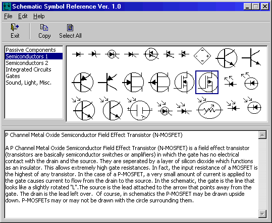
Using the reference is very simple. All you need to do is move your mouse over the symbol you want information about and click. Note that when you move your mouse over any symbol, an explaination of what is appears below the graphic. To move between the different catagories, just click the approiate link under "Catagories", or use the "Next" and "Previous" links to surf through the various catagories. Remember that there are a few variations in the way different people draw their symbols. For example, some use and to mean the same thing. This reference tries to provide the industry standard symbols.
If at some points it seems like I am repeating myself, I am. This is so that you can look up the symbols in any order you wish. I have also left space in several of the image maps in case there are new symbols introduced. Please note that the symbols are in no particular order. Nevertheless, the reference is still very easy to use as everything is plainly visible.
I think that you should really view this in 800x600 resolution. I tried to make it work in all resolutions, but this is the way it turned out. It should still work fine in 640x480, but there will be a lot more scrolling. Anything less than 640x480 will probably make this reference totally
unusable.
| Connections, Wires, Passive Components, etc... Semiconductors 1 Semiconductors 2 ICs Gates Sound, Light, Motors, Miscellaneous | 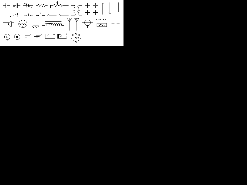 | |
| | ||
The most popular circuits of today, yesterday and all time can be found below.
| When | Circuit | Views |
| Today Tuesday, August 25, 2009 | 12VDC To 120VAC Inverter | 64 |
| Automatic 12V Lead Acid Battery Charger | 40 | |
| Yesterday Monday, August 24, 2009 | 12VDC To 120VAC Inverter | 575 |
| FM Transmitter | 380 | |
| Of All Time | 12VDC To 120VAC Inverter | 520,673 |
| FM Transmitter | 385,036 |
Auto | Back to the top of this document |
| Detailed View: On/Off | |||||
| Circuit | Author | Views | Rank | Comments | Marker |
| Automatic Headlight Brightness Switch | 79,601 |   | 48 | * | |
| Car Alarm Arming Horn Beep Canceller NEW! | bob | 35,424 | | 4 | * |
| Wireless Auto Tachometer | 125,537 | | 50 | ||
Computer | Back to the top of this document |
| Detailed View: On/Off | |||||
| Circuit | Author | Views | Rank | Comments | Marker |
| Computer Controlled Frequency Counter/Logic Probe | Richard van Wyk | 54,157 | | 29 | * |
| Parallel (Printer) Port Interface | 109,612 | | 67 | ||
Light/Laser | Back to the top of this document |
| Detailed View: On/Off | |||||
| Circuit | Author | Views | Rank | Comments | Marker |
| 12VDC Fluorescent Lamp Driver | 148,413 | | 53 | * | |
| 3 Channel Spectrum Analyzer | 48,100 | | 11 | ||
| 40W Fluorescent Lamp Inverter | Bart Milnes | 110,250 | | 55 | * |
| Adjustable Strobe Light | 95,774 | | 24 | ||
| Black Light | 93,800 | | 26 | ||
| Colour (Sound) Organ | 100,274 | | 25 | ||
| Fantastic Atom Expander | 59,642 | | 21 | ||
| Flash Slave Trigger | 76,561 | | 15 | * | |
| Infa-Red Remote Control | 222,680 | | 199 | * | |
| IR Remote Jammer | Carl | 85,857 | | 96 | * |
| LASER Transmitter/Receiver | 128,827 | | 80 | ||
| LED Chaser | 131,958 | | 72 | * | |
| LED Thermometer NEW! | 65,327 | | 14 | * | |
| Light/Dark Detector | 99,602 | | 81 | * | |
| Simple Colour Organ | 42,792 | | 7 | * | |
| Strobe Light | 111,699 | | 25 | * | |
| TRIAC Light Dimmer | 162,864 | | 50 | ||
Major Projects | Back to the top of this document |
| Detailed View: On/Off | |||||
| Circuit | Author | Views | Rank | Comments | Marker |
| 142,358 | | 119 | * | ||
